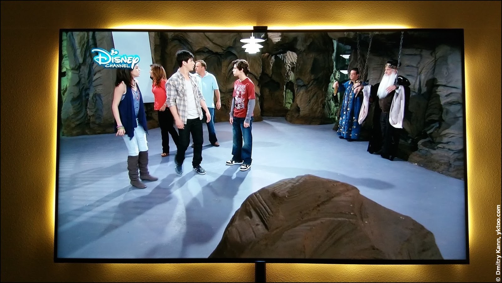
Being quite happy with my 75 inch whopper Samsung UE75HU7500, the only thing I wanted to do about it was giving it ambient backlighting. When watching TV in complete darkness your eyes get quickly tired because of the stark contrast between the bright screen and its dark surroundings. Even though this device features an ambient light sensor, which is used to automatically adjust the screen brightness, the contrast is still all too harsh.
And when the wall behind the TV is lit, the boundary between the picture and the darkness is blurred, and that’s definitely a relief for the eyes.
More details and geek porn are under the cut.
The backlighting
I purchased three IKEA Dioder sets, warm white, each consisting of a 12 volt driver, four LED strips 25 cm (10") each, and connection cables.
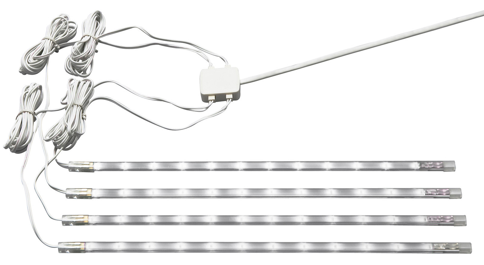
The strips can be affixed on a surface in two ways: with sticky foam pads or with special metal braces. I’ve decided to go with the latter option, and involve the TV’s back-cover mounting screws for that. The screw heads are some 2-4 mm (depending on the side) under the surface of the cover, so I made appropriate washers from an aluminium tube (inside diameter 4 mm):
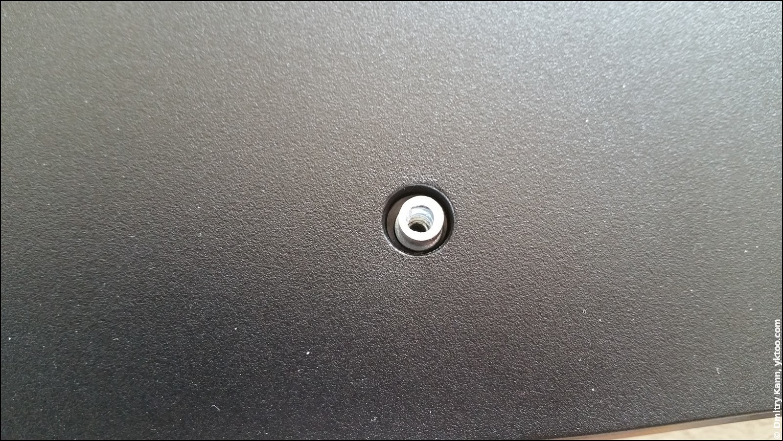
Obviously, you’ll also need somewhat longer screws, as they need to go through the brace and the washer and securely reach the socket:
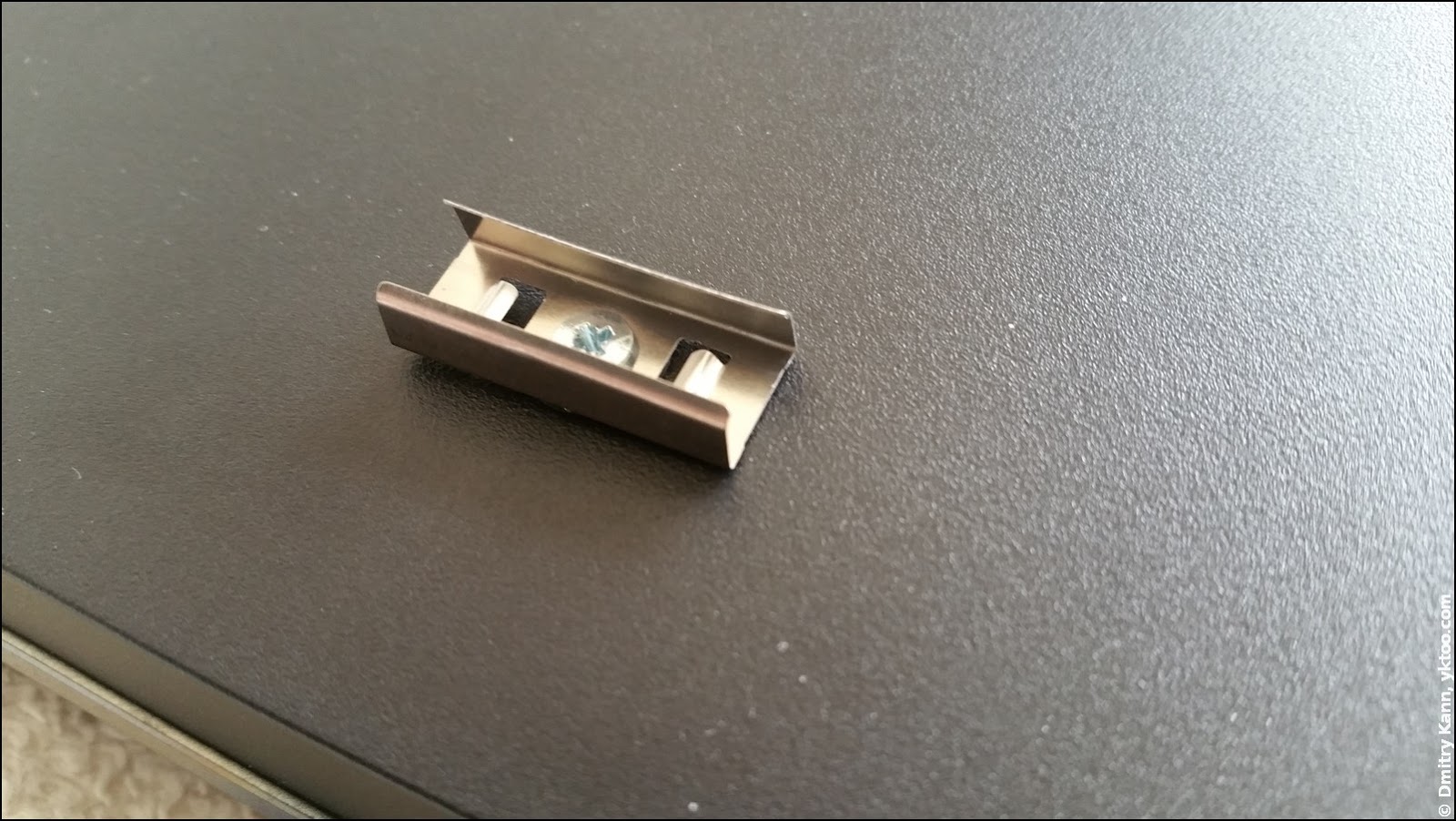
My initial design included 6 segments of two strips each: two at the top, two at the bottom, one at each side, which adds up to exactly 12 strips (3 sets × 4 pcs). Therefore I had to make five connection cables. The latter are made from the short ones provided with the set, so what you need to do is to replace the wire with a longer one:

The sides of the back-cover are slanting, but the screws are perpendicular to the screen, thus the side strips are mounted at an angle to the cover.
Once the strips are securely fixed, it’s a good idea to test it with an external 12 V DC adapter (it must provide at least 1 A). It’s no rocket surgery, so I got it right the first time:

Powering it up
The main challenge that kept me from implementing this originated from the wish that the backlighting automatically goes on and off with the TV set. I’ve even bought a solid-state relay from eBay, which I planned to use to switch the main power of the DC adapter. The control terminals would then be driven from the TV’s USB (the SSR’s control voltage can range 3 to 20 volts, so the 5 volts from the USB would suit perfectly).
But at a later moment I’ve got a crazy idea to power the strips directly from the TV’s power supply. 12 volts is a very common voltage with electronics, so I’ve decided to peek in the whopper’s internals.
Below is hardcore geek porn!
To remove the back-cover, one needs to unscrew 10 screws along its edges plus another one next to the component input. Quite expectedly, it isn’t very crowded inside the device:

On the left is the CPU/video processing board and a small solitary fan above it. It’s not clear what it’s supposed to cool, I guess it simply makes sure the air inside is circulating.

In the middle is a controller board for the backlight and the LCD panel.

On the right is a power supply for the above. This one is awe-striking. The whole board is very thin to make the TV as flat as possible, it’s hardly more than an inch thick:

The boards seem to be small, but keep in mind the TV is almost two by one metre. So the last board, for example, is about the size of an A3 sheet.
The bottom view of the power supply:

After a careful examination of the board I’ve found a power source output marked as 13 V, in fact it provided some 12.7 volts. That is perfect for the LED strips I have. It’s quite difficult to state the current that you may draw from it, but judging by the six (!) wire leads connecting it to the backlight controller, it’s pretty mighty. Also if you consider the power required by the panel backlight, I’d say it should be capable of supplying some 10-12 amperes.
And my home-brew backlighting would be content with only 800 mA (as one set of four strips draws some 240 mA).
So I’ve decided to take this risk and connect the LED cable to the output marked 13V:

The cable leaves the TV via a slit intended for the foot (which is not used as the TV is hanging on the wall):
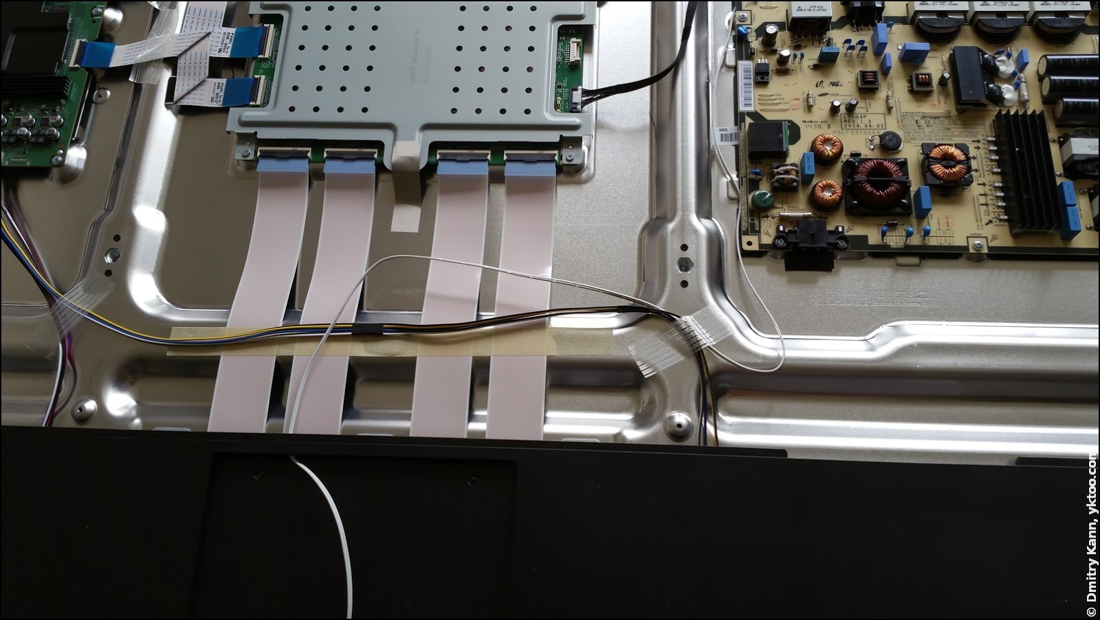
In close-up:

All I needed to do was plugging it into the strip (I used a cable from the set), and we’re on:

But then I didn’t like the “gaps” at the top and the bottom; moreover, I thought, we can add a bit more light. So I ended up buying another “Dioder” of four strips. I inserted one in the middle at the top, replacing the wire; another one, likewise, at the bottom; and also one at each side.
You’ve already seen the result on the first photo.
Surprisingly enough, it all operates exactly as intended. The backlighting goes on the same instant as you switch the TV on, and goes out in about five seconds after you press the power button on the remote.
See also
- 4K UHD TV Samsung UE75HU7500: a complete review:
 — world’s fastest URL shortener
Comments